in which the dummy cameras are indicated as CAM2 and CAM5. These are not usually connected so arrange these cameras simply to create a healthy sense of paranoia.

The two larger cameras inside the license server box transmit bad pictures, so use the smaller one that's inside the license server box.
Therefore the exhibit contains a total of four good quality cameras (six Internet cameras total), but only three of them are external to the rack, and only one that's in the rack produces a high quality picture. The ones in the rack must be fastened down during shipment, and positioned appropriately upon arrival. The three external cameras to be mounted on the wall are numbered CAM1, CAM3, and CAM4, whereas the ones in the rack are CAM2, and CAM5, and the covert spy camera. The covert spy camera does not have such a number on it, and is glued to the top of the computer in the rack. CAM2, and CAM5 receive DC power from within the rack, but the spy camera receives power from a separate power supply to be plugged in behind the rack. CAM2 and CAM5 are poor quality cameras and are not connected to anything else. They are put in the rack as "fake cameras" so to scare away criminals who might otherwise attempt to STEAL seating services. Thus CAM2 and CAM5 are present for visible deterrence, whereas the covert spy camera is the camera that actually does the monitoring from inside the rack.
Three holes are drilled in the floor for cabling for the chair, for the 3 legs of the chair that have wiring. The legs of the chair cover most of the area of these holes. I use a dremel tool to make each of these holes an irregular shaped hole so that each one is just big enough for the plug that will pass through it, and for the cable beyond the part that's under the leg of the chair.
Cabling runs under the raised floor and the chair legs are screwed to the raised floor by screws from underneath.
The chair is made of solid oak, so be certain to use the correct screws so that the oak does not split, and so that the screws do not break off (since it is very difficult to screw into solid oak).
The raised floor assembly is usually held up on sawhorses during wiring of the chair, so that, from underneath, the wiring and screwing down of the chair can be done. Then the raised floor is lowered down onto the main floor, after connecting to an AC outlet (if there is one under the floor), and the TV stand and relay rack are placed on the raised floor after it is lowered down.
Two additional holes are needed, one for all the cables that go to the relay rack, and another for all the cables that go to the TV stand. These two holes can be very big, and may be round, for simplicity, so that they can simply be drilled with a 2 inch diameter hole saw. Thus there should be a total of five holes drilled in the raised floor, two big round ones (one for the relay rack and one for the TV stand), and three small irregularly shaped ones (for the chair), each being just big enough for the corresponding cable plug that will pass through that hole.
One cable from the chair is a "monster cable" 12 guage twinlead with banana plugs (red and black) on the end. Run this cable under the floor and back up out of the relay rack hole. Later, once the relay rack is placed on the floor, this cable will plug into the outlet for the 1 farad "high voltage capacitor" section of the rack (this section of the rack is the second from the bottom, at the back of the portion that is labelled "LICENSE MANAGER" on the front of the rack). Be sure to observe correct polarity on this high power cable, e.g. be sure to connect red to red, and black to black.
Another cable from the chair has a 120 VAC standard wall plug on the end. For safety, it has a ground pin, and must be plugged into a properly grounded outlet. For this purpose, and for the rest of the wiring, I have provided two professional full length Hammond power strips, each having eight outlets. These are both to be mounted under the floor, facing sideways, each on one of the two by four inch planks.
The power strips are typically cascaded (one plugged into the other), and the head-end power strip is plugged into the relay rack, so that the entire exhibit can be turned on or off with a single switch located at the back of the 19 inch relay rack at the top. The power strips plug into this top portion of the relay rack from the back. The relay rack itself is then plugged into a properly grounded outlet to ensure safety. THE OUTLET MUST BE PROPERLY GROUNDED!
The third remaining cable from the chair is a PARASEAT BUS cable. It has an RJ45 plug on it, so it looks just like an ethernet cable, but it is not an ethernet cable. It uses the proprietary PARASEAT protocol (parallel port seating protocol) designed by Steve Mann, Assistant Mailroom Clerk of EXISTech Corporation (a Federally incorporated company). This cable goes under the floor and back up and out to the 19 inch relay rack and connects to the parallel port PARASEAT BUS adapter on the computer in the relay rack. Note that the PARASEAT BUS adapter on the computer is connected to the computer's parallel printer port, and there is a wye connector there that allows two items to be plugged into the PARASEAT BUS. Since it is a true bus (e.g. the two outlets are connected in PARAllel), it does not matter which of the two items is plugged into which of the two sockets on the parallel port adapter, so the seat can be plugged into either of these two outlets.
There are two sites (known as PARASITES) on the PARASEAT bus, both connected in parallel. One PARASITE is the internet chair, and the other PARASITE is a collection of components embedded within the 19 inch relay rack itself. Therefore, online one of the two PARASEAT BUS outlets should be available for the internet chair, and the other PARASEAT BUS outlet will be already occupied by another RJ45 plug.
The 19 inch relay rack requires two ethernet connections, one for the computer, and one for the security system comprising cameras CAM1 to CAM4. CAM1, CAM3, and CAM4 have BNC connectors that should be plugged into the security system (a small black metal box on top of the computer, having four BNC connectors on it). It may be necessary to drill additional holes into the floor, or the side of the floor raisings (the two by four inch planks) for the CAM1, CAM3, and CAM4 wiring. The spy camera in the server rack box is connected directly to the computer.
Make sure not to confuse the ethernet connections with the PARASEAT BUS connections since both use the same kind of plug.
The chair should face the TV stand, so that a person seated thereupon can comfortably watch the TV set. (See http://wearcam.org/seatsale/index.htm for pictures of the setup.) The TV set has a 120 VAC power cable, and a standard VGA video cable, both of which run under the floor. The power cord plugs into one of the Hammond power strips, and the VGA cable plugs into the computer by way of a VGA extension cord. The movies playing on the TV set incorporate a sound track, so there is provided a pair of black multimedia speakers that plug into the computer by way of an extension cable for stereo 1/8 inch connectors, this wire running under the floor from the computer in the 19 inch relay rack to the TV stand.
The relay rack must be located close enough to the internet chair that the warning buzzer is audible to a person seated thereupon.
Sound levels in the exhibition space must be sufficiently low that the warning buzzer is clearly audible.
SeatSale uses a high performance computer system and must therefore be powered properly to avoid corruption of the file system. In particular, make sure that the AC outlet to which the exhibit is connected is reliable, and that it will not accidentally be unplugged or shut off during usage. If there is any question as to the quality of the AC outlet an outlet on an Uninterruptable Power Supply should be used. The apparatus is designed to "Fail Secure" (e.g. the spikes unretract upon loss of electrical power in order to prevent theft of Seating Services by the inducement of a power failure).
SeatSale must be shut down using the proper procedure described further down in this document, in order to avoid corruption of the file system.
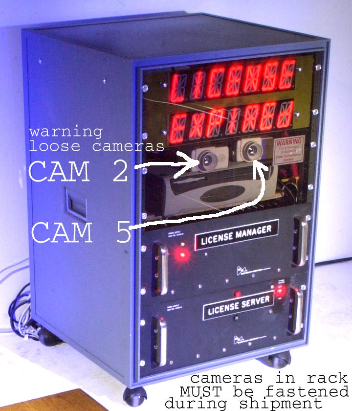
The two dummy
"fake" (e..g poor picture quality)
cameras in the 19 inch relay rack must be fastened prior to shipping,
and arranged upon arrival at the new site. The relay rack cameras are shown
in the following figure:
in which the dummy cameras are indicated as CAM2 and CAM5.
These are not usually connected so arrange these cameras simply to
create a healthy sense of paranoia.
The relay rack cabinet must be connected to a properly grounded AC power outlet. The heavy 12 guage cable from the seat to the relay rack must be connected properly and securely, and must have proper strain relief so that it does not accidentally get pulled loose during operation.
Steve Mann, mann@eecg.toronto.edu, Feb 2001